A float valve is the simplest automatic fill control available — a buoyant float riding the water surface, mechanically opening and closing the supply as the tank drains and refills. No power required. No software. No failure mode that knocks out the tank when the power is off. For a storage tank whose entire purpose is to hold water for when something else has failed, that is a significant advantage over electronic controls.
The function sounds trivial. It is not. As one trade association puts it, manufacturers have been trying to perfect the float valve for the last 130 years — and the three failure modes that come from getting it wrong are still: valve won't shut off, premature seat wear, and water hammer. This guide covers how to avoid all three.
The Four Float Valve Types
| Type | Head Loss | Min Pressure | Cost | Best Size Range |
|---|---|---|---|---|
| Direct-acting | High | ~10 PSI | $ | ½" to 1½" |
| Equilibrium | Low | Low OK | $$ | ½" to 2" |
| Pilot-operated | Very low | ~15–20 PSI | $$$ | 1¼" to 12"+ |
| Electronic | Varies | Varies | $$–$$$$ | Any |
Part 1 — The Air Gap: What Most Tank Fill Installations Get Wrong
The air gap requirement is defined in the International Plumbing Code (§ 608) and IRC (§ P2902), referencing ASME A112.1.2:
| Supply Pipe Size | Minimum Air Gap (2×D) | Note |
|---|---|---|
| ½ inch | 1 inch | 1" floor governs |
| ¾ inch | 1.5 inches | 2×D governs |
| 1 inch | 2 inches | 2×D governs |
| 1¼ inch | 2.5 inches | 2×D governs |
| 1½ inch | 3 inches | 2×D governs |
| 2 inch | 4 inches | 2×D governs |
| 3 inch | 6 inches | 2×D governs |
| 4 inch | 8 inches | 2×D governs |
| Per ASME A112.1.2 as referenced in IPC § 608 and IRC § P2902. Local codes may require larger gaps. Confirm with your water purveyor or plumbing official before installing. | ||
The Three-Part System: Valve + Air Gap + Overflow
The air gap only works if the water level never reaches it. If the float valve fails open and the overflow can't pass the incoming flow, the level rises past the rim and the air gap is submerged.
How to Detail It Correctly
- Mount the valve so the discharge outlet is entirely above the flood level rim
- Verify vertical distance is at least 2× supply pipe inner diameter, minimum 1 inch
- Do not extend a fill tube from the valve outlet down into the tank. This defeats the air gap silently — and people add it thinking it reduces splashing
- Confirm nothing can rise into the gap — no hose draped over the edge
- Verify annually the air gap is still intact — modifications can defeat it silently
Part 2 — Sizing: The Four Numbers You Need Before You Buy
| # | Specification | Why It Matters |
|---|---|---|
| 1 | Required fill rate (GPM) | Determines port size. Too small and the tank never keeps up with draw-down rate. |
| 2 | Running pressure at valve inlet | Direct-acting valves incur high head loss and struggle at low pressure. Pilot-operated valves need a minimum pressure to function. |
| 3 | Maximum static shut-off pressure | The static pressure when no demand is on the system — higher than running pressure. The valve must seal against this. Getting this wrong causes the valve to dribble forever. |
| 4 | Connection size and mounting geometry | Match the tank fitting and maintain the air gap geometry at the discharge outlet. |
The Velocity Rule — Keep Inlet Velocity in the 2 to 3 m/s Band
| Inlet Velocity | Consequence |
|---|---|
| Under 2 m/s (6.6 ft/s) | Ideal — quiet, low wear |
| 2 to 3 m/s (6.6–9.8 ft/s) | Acceptable — the design band manufacturers size to |
| Over 3 m/s (9.8 ft/s) | High noise, accelerated seat wear — seat chatter destroys seats quickly |
| Source: Association of Tank and Cistern Manufacturers | |
Which Type for Which Situation
| Situation | Recommended Type |
|---|---|
| Small tank, intermittent top-up, adequate pressure | Direct-acting — cheapest and simplest |
| Tank in constant or heavy demand | Equilibrium or pilot-operated |
| Low or falling supply pressure | Equilibrium — float doesn't fight line pressure |
| High flow, large tank, fire reserve | Pilot-operated |
| Long dedicated supply run to remote tank | Pilot-operated with slow-close feature |
| Chemical / corrosive service | All-plastic — no metal parts in solution |
| Potable water storage | NSF/ANSI 61 and 372 certified, verified air gap |
| Emergency water tank | Mechanical (not electronic) — works without power |
Part 3 — Water Hammer
A float valve that closes rapidly from full open to shut stops a moving column of water abruptly. That energy becomes a pressure surge — water hammer. An oversized float valve on a long supply run can be loud and damage piping.
| Configuration | Hammer Risk | Mitigation |
|---|---|---|
| Short supply run, building with multiple fixtures | Low | Standard valve usually fine |
| Long dedicated run to remote tank | High — no pressure relief points | Slow-closing or delayed-action valve; surge arrestor |
| High flow, fast-closing valve | High | Pilot-operated with delayed-action close |
| Rapid on/off cycling | Cumulative wear | Delayed-action float — tank draws to lower level before reopening |
If your valve chatters or cycles every few minutes, a delayed-action float is the solution. It lets the tank draw down to a set lower level before reopening — reducing cycling, seat wear, and hammer events, while also promoting water turnover rather than continuously topping off the same stagnant volume.
Part 4 — Materials and Potable Certification
| Material | Best For | Watch For |
|---|---|---|
| Brass / bronze | General potable and industrial water service. Durable, good seat life. | Lead content — check NSF/ANSI 372. Not for corrosive chemicals. |
| Stainless steel | Aggressive water, high temperature, long service life. | Cost — overkill for most residential applications. |
| All-plastic | Corrosive chemicals — no metal in solution. Rated to 80 PSI. | Lower pressure and temperature limits than metal. |
| Hollow float (plastic/copper) | Any application | Waterlogging — most common single component failure. Inspect annually. |
| EPDM seat | Fresh water, mild chemicals | Chlorine and chemical dosing degrade some elastomers. |
Top Picks

- Aluminum housing holds up to outdoor and livestock conditions
- Expansion brackets fit varied tank wall thicknesses without drilling precisely
- Garden hose thread — no adapters needed for most outdoor hookups
- Made in USA with nationwide parts availability

- NPT thread fits permanent plumbed setups directly
- Metal construction handles rough livestock environments
- Compact size fits most standard stock tanks and troughs
- Little Giant name — parts and service widely available
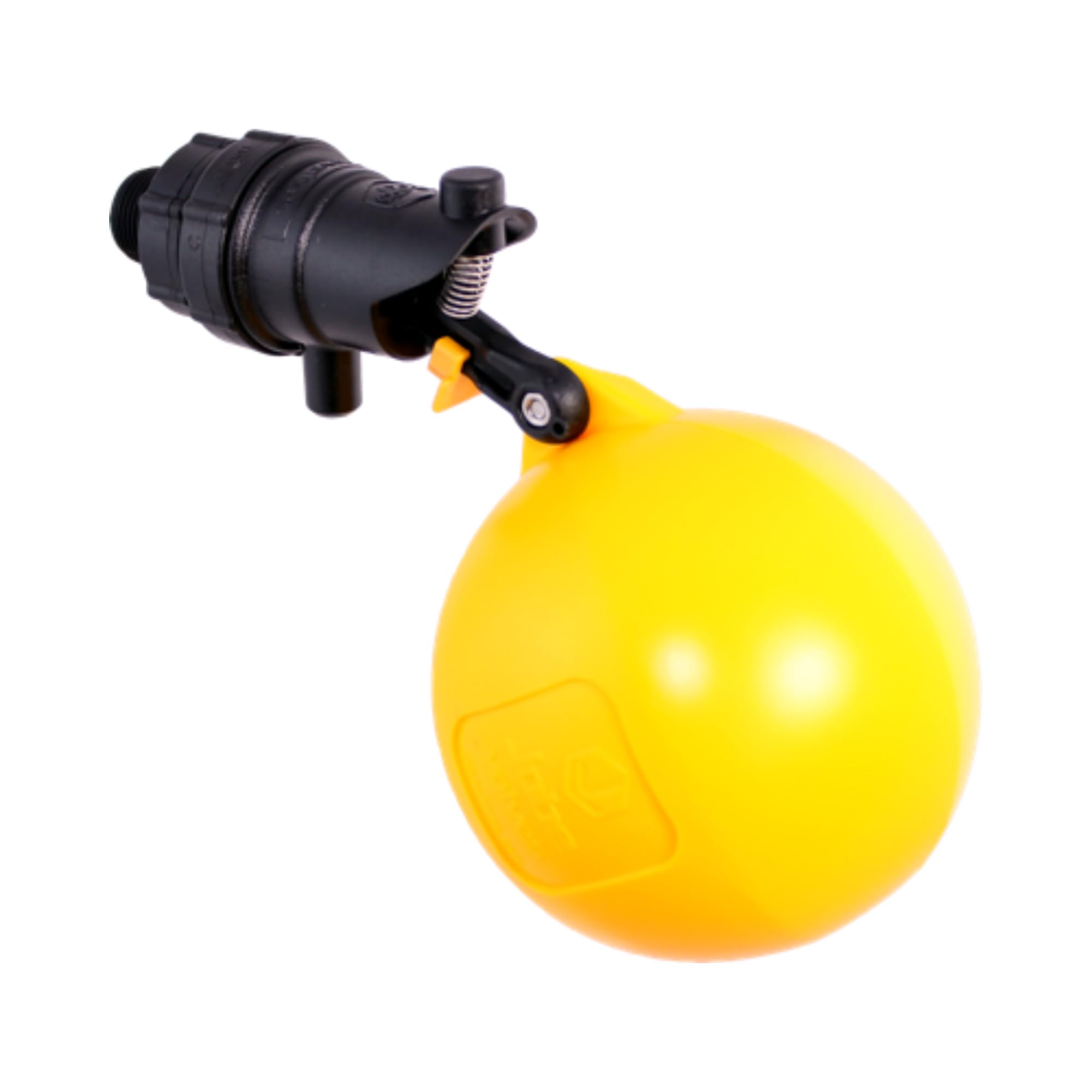
- NSF-spec construction — suitable for potable water contact
- 10 bar (145 PSI) rating — well above most agricultural supply pressures
- 2-year warranty — longest in this livestock category
- Fits tire tanks and standard troughs
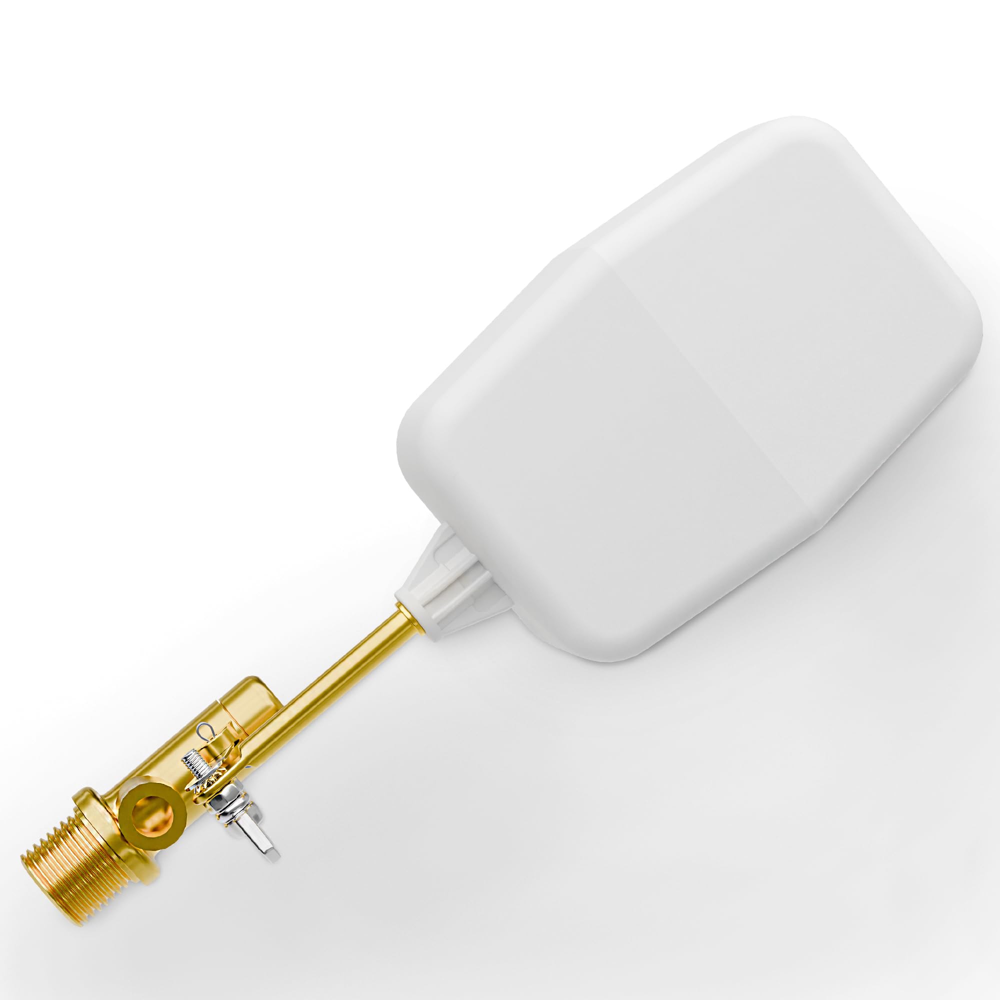
- 125 PSI rating — handles high-pressure supply lines without dripping
- Wingnut adjustment for precise flow tuning at installation
- Brass body for long service life in outdoor conditions
- Compatible with extensions and reducers for flexible hookups
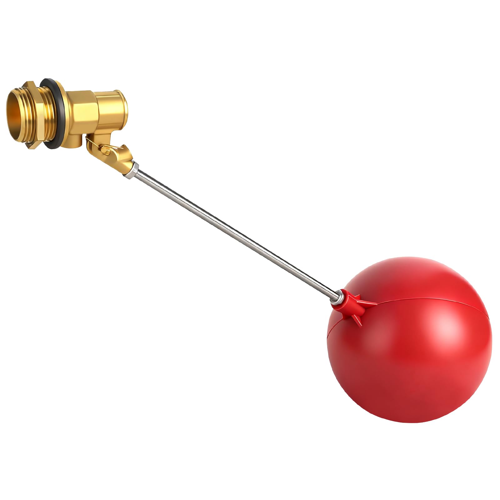
- 304 stainless resists corrosion in humid, coastal, and outdoor environments
- Works on both pressurized and gravity-fed tanks
- Includes mounting hardware — ready to install out of the box
- 85 PSI rating handles most residential and agricultural pressures

- Lowest cost in the roundup for basic autofill function
- Standard ¾" NPT fits most common tank fittings
- Lightweight — easy to move between seasonal locations
- Good fit for low-use applications where a metal valve is unnecessary

- Designed specifically for PVC and poly-wall small tanks
- Expansion brackets fit varied wall thicknesses
- Compact 1" H profile fits tight tank installations
- Little Giant brand with nationwide parts availability

- G × NPT adapter solves mixed thread standard retrofits
- Brass + stainless construction — more durable than plastic alternatives
- Adjustable ball for tuning flow to your recovery rate
- Fits large storage cisterns and farm troughs with non-standard threads
Troubleshooting Guide
| Symptom | Likely Cause | Fix |
|---|---|---|
| Won't shut off; overflow runs | Debris on seat; worn washer; waterlogged float; undersized for shut-off pressure | Clean seat. Replace washer. Lift float — feel for water inside. Verify shut-off pressure rating vs static line pressure. |
| Float sits low or partly submerged | Waterlogged float — pinhole has let water in | Replace the float. A waterlogged float cannot generate closing force. |
| Loud bang when closing | Water hammer — rapid closure on long supply run | Slow-closing or delayed-action valve. Surge arrestor. Verify velocity is within 2–3 m/s. |
| Chattering or buzzing while filling | Seat chatter — oversized valve or excessive velocity | Resize down. Over 3 m/s destroys seats quickly. |
| Tank fills too slowly | Valve undersized; insufficient running pressure; fouled strainer | Check running pressure at valve. Upsize bore. Consider equilibrium type for low-pressure supplies. |
| Valve cycles every few minutes | No drawdown delay — reopens on smallest level drop | Delayed-action float mechanism — tank draws to lower level before reopening. |
| Tank water quality poor | Continuous topping-off; stagnant volume at surface | Drawdown-delay control forces complete turnover before refilling. |
The Five-Minute Annual Inspection
- Lift the float. Does the valve shut off cleanly and completely?
- Push it down. Does it open freely without sluggishness?
- Check the float for waterlogging. Shake it — water rattling inside? Feel for extra weight. Replace if waterlogged.
- Verify the air gap is still intact. Discharge outlet above the flood level rim by at least 2× pipe diameter? Modifications can defeat this silently.
- Confirm the overflow is clear and still routes to a visible discharge point.
That is the complete inspection — it catches nearly every failure in the troubleshooting table before it becomes a flooded pad or a boil-water advisory. Always install an isolation valve upstream so you can service the float valve without shutting down the entire supply line.
International Plumbing Code § 608 and IRC § P2902 · ASME A112.1.2 · NSF/ANSI 61 and 372 · Association of Tank and Cistern Manufacturers, "Float Operated Inlet Control Valves — Their Ins and Outs" · Flomatic Valves product data · AKMueller manufacturer literature · U.S. Plastic Corporation all-plastic float valve data · West Virginia Bureau for Public Health cross-connection manual · Municipal cross-connection ordinances
Frequently Asked Questions
Most IBC totes have a 2-inch male NPT fill port at the top. Thread a ¾-inch or 1-inch float valve into the top port (use a reducing bushing if needed) with the valve body inside the tote and the supply water inlet above the top rim. This naturally creates the required air gap if the valve discharges downward inside the tote with the outlet above the flood level rim. The float arm hangs down inside and closes the valve as the level rises. See our camlock fittings guide for connecting the outlet at the bottom.
It depends on fill rate required, not tank size. If you draw 50 gallons per day and have 24 hours to refill, a ½-inch valve is more than adequate. If you need to refill 500 gallons in 2 hours, you need ~4.2 GPM — check your ¾-inch valve's flow rating at your available supply pressure. Calculate required fill rate in GPM first, then find a valve that delivers that flow within the 2–3 m/s velocity band.
Three causes in order of frequency: (1) Velocity too high — valve undersized or at excessive flow rate. Over 3 m/s inlet velocity creates high noise. (2) Seat chatter — the valve is hunting between slightly open and closed, which happens when oversized or at the wrong pressure point. (3) Water hammer — a bang when the valve closes, from rapidly stopping a moving water column on a long supply run. Fix for 1 and 2: resize. Fix for 3: slow-closing or delayed-action valve, especially on dedicated remote supply lines.
For a small indoor tank at low flow — technically yes. In practice, toilet ballcocks have lower shut-off pressure ratings than purpose-made float valves, narrower water level range, and plastic bodies that degrade faster outdoors. For anything beyond a small backup tank, use a purpose-made valve. The Kerick MA075 and Hudson 1C cost only slightly more and are designed for the application.

Water and wastewater treatment professional with 18+ years of hands-on experience. Has specified, installed, and maintained float valve fill controls on agricultural, industrial, and municipal water storage applications. Grade IV Wastewater Certification holder.